The first one is to precise the specifications of the fil-ter which are the center frequency of 37 GHz and the passband bandwidth 110 of MHz or the fraction-al bandwidth FBW. One can use Agilent ADS or Microwave Office as RF design software tool for simulation and verifying the results.
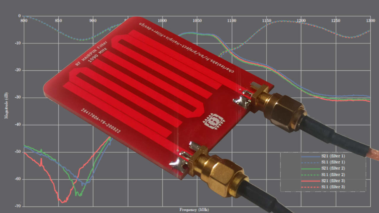
Charles Labs Hairpin Filter Design
Simulation and measurement result shows that the proposed microstrip hairpin filter works at 923 MHz with bandwidth of 4 MHz from simulation result whereas from measureme nt r sult 75 MHz.
. This flow combines yield analysis in Cadence AWR Microwave Office software practical topologies synthesized by Cadence AWR iFilter filter synthesis wizard and design validation using the Cadence AWR AXIEM 3D planar. B Filter Design Specification- 1 Center. The layout is automatically created.
I need to know how to start the design what things i need to know before doing the design. The example designs are a classic hairpin filter with a bandwidth of 37 to 42 GHz and a 1 to 8 GHz directional coupler using the Schiffman sawtooth or zig-zag technique to reduce the size. DESIGN OF THE HAIRPIN BAND PASS FILTER A The design of band pass filter involves two main steps.
This paper proposed a microstrip hairpin filter wi th via ground holes for 923 MHz RFID application. How design hairpin filter hi everyone im going to design a hairpin bandpass filter. To run the openEMS simulation you need to install openEMS through octave or MATLAB and Paraview optional.
Rebar Development Length Calculator is a web application that supports the design of post-installed rebar in concrete applications by calculating the necessary tension and compression development lengths required in accordance with ACI 318-19 ACI 318-14. 1GHz Hairpin BPF design. In hairpin filter space is saved by folding the resonator which is half wavelength long.
I have made and tested hairpin filters for 902 1152 1296 and 1440 MHz all using the same dimensions changing only the length of the hairpin legs. The concept of hairpin filter is same as parallel coupled half wavelength resonator filters. This application note illustrates a design flow to on a hairpin bandpass filter BPF with a target center frequency of 58GHz.
To allow for bending a sliding factor is introduced. The design hairpin resonator have a line width of 1mm and a sepration of 2mm between the two arm. Hairpin Filter is one of the most popular microwave frequency filters because of it is compact and does not require grounding.
Also the hairpin design is simple. Integrated as a wizard within the AWR Design Environment iFilter keeps your filter designs and their evolution a part of the entire managed circuit design project. Note PCB components designed using the design function operate around the specified frequency with a 10-15 tolerance.
This makes the design compact. This video demonstrates a rapid and accurate flow for designing microstrip cross-coupled filters using Nuhertz filter solutions and NI AWR Design Environment. Can any of you recommend a tutorial or lab sheet or books that i can download it as my references.
In this article 1GHz Hairpin type of BPFBand Pass Filter design is explained. I need to design a microstrip hairpin stripline bandpass filter for UWB application. Jul 20 2006 11 B.
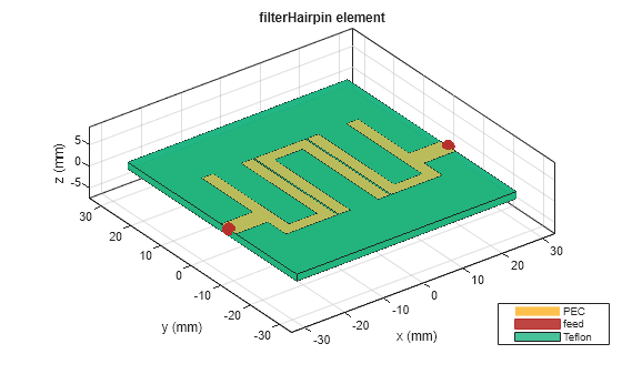
Length in Figure 11 provides a simple recipe for filter design. You can change the simulation parameters in the setup block. By folding the parallel coupled half wavelength resonators in to u shape hairpin resonator is obtained.
The hairpin filter was designed and simulated using Agilent ADS 13 1 with planar EM analysis using Sonnet Lite 2. Im new to this software cst microwave design so i really need help regarding this software. Design of a microstrip bandpass filter for 3 1 10 6 ghz.
The coupler used a design-rule-based. The figure depicts RF simulation circuit for 1GHz Hairpin BPF. Filter designfilter2e9 FBW BandWidth RippleFactor Ripple.
The advantage of hairpin filter over end coupled and parallel coupled microstrip is its low space utilization. Filters are compact structures. Design of microstrip hairpin bandpass filter for 29 GHz 31 GHz s-band radar with defected ground structure January 2019 Malaysian Journal of.
1 The first step is to select an appropriate low pass prototype. Use the design function to design a 3rd order hairpin filter with a RippleFactor of 01 dB and 20 fractional bandwidth and visualize it. Design of conventional hairpin filter Hairpin line filters are compact structures.
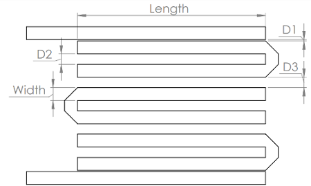
The dimensions in Table 1 and the curve of frequency vs. The filter is designed at center frequency of 58 GHz with a fractional bandwidth of 345. A band pass filter is designed to have a fractional bandwidth of 028 at a centre frequency of 25.
Im just a student without the knowledge of microstrip design. A 37 to 42 GHz hairpin filter This filter was designed for a flat response over the 37 to 42 GHz band with low inser-tion loss and return loss better than 16 dB across the. Run the file to launch the openEMS analysis may take a while.
The dimensions are identified in Figures 9and 10 and listed in Table 1. The filter is synthesized on 0020 RO6006 Er615 material with 12 oz. By adding the via ground holes the di mension of the filter is reduced to 37.
By the way i will use the ansoft designer. QUCS for Filter Design Introduction QUCS or Q uite U niversal C ircuit S imulator is a freeware utility that allows you to draw circuit schematics and perform AC DC simulation noise simulation for S-parameters and AC simulations S-parameter simulation and a whole lot more upon them. This frequency is presenting for wireless LAN application and operates in the ISM band Industrial Scientific and Medical application.
2 The choice of type of response including pass band ripple order of filter and number of reactive elements will depends on the required specifications. 1st Technique Conventional Hairpin configuration uses folding of the normal λ2 resonators into U shape. Report Application Issues or Provide Customer Feedback.
Ann modeling of microstrip hairpin line bandpass filter. The AWR integrated filter synthesis module iFilter seamlessly runs within Microwave Office. Hpfilter design___NameValue designs a hairpin filter with additional options specified by name-value arguments.
22 Structure of bandpass filter The design of band pass filter involves different steps.

Pdf Design Of Microstrip Hairpin Band Pass Filter Using Defected Ground Structure And Open Semantic Scholar
2
Design And Analysis Of Hairpin Micro Strip Line Bandpass Filter Matlab Simulink

Hairpin Micro Strip Line Band Pass Filter Reflectionless Filter Design Simulation Results In Cst Youtube
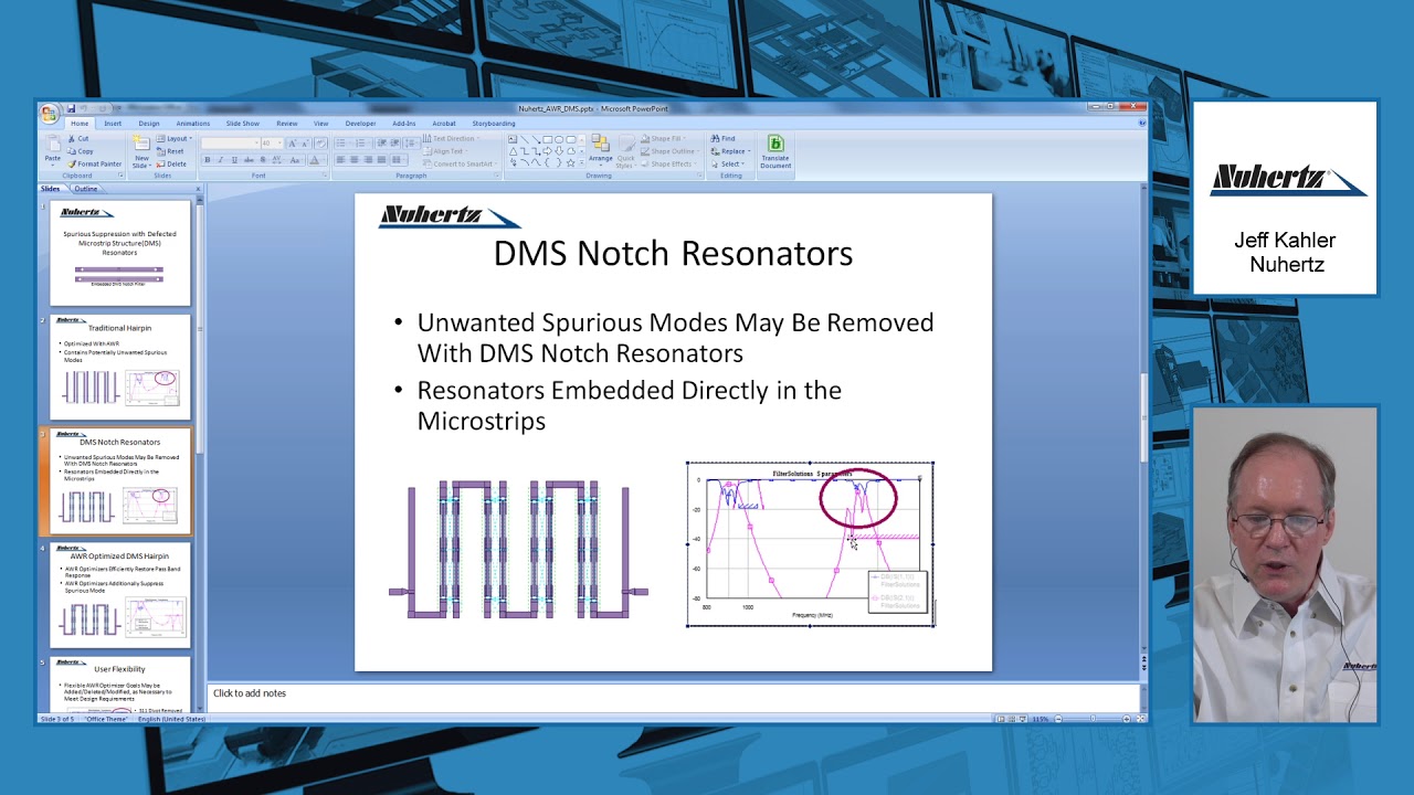
Design Example Nuhertz On Dms Hairpin Filter Youtube
Charles Labs Hairpin Filter Design

Pdf Design And Simulation Of Hairpin Band Pass Filter For Different Substrate Engineering Research Publication And Ijeas Academia Edu

Pdf Design And Analysis Of A Bandpass Hairpin Filter
0 comments
Post a Comment